YINGFENGMulti-head cutting system
Get mCAD
← Back to homepageFrom design preparation to production

Connect drawings, nesting and multi-head cutting

YingFeng connects mCAD design and nesting with the main program’s production workflow. Prepare part geometry, quantities, sheets and head assignments, then check toolpaths, processes and jobs under the current machine conditions.

01

A layout needs an executable cutting plan

When drawings, quantities and machine settings are handled separately, a compact layout may still be impossible to cut. Shared rails, head travel, physical spacing and tool processes need to be checked together.

02

Start with the actual material and machine

For soft sheet stock cuttable with an oscillating knife, such as foam and sponge. Honeycomb, sealing and insulation applications require confirmation of material thickness, blade suitability and a test cut.

Prepare single-head or multi-head plans for the actual machine. Before network transfer, verify the target’s heads, sheet and physical limits, then confirm on-site production conditions in the main program.
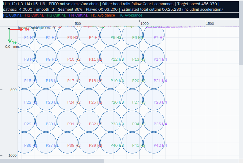
03 · Interactive illustration; no live machine control

From nesting preparation to a production job

Illustrative animation, not a live machine. Actual processing depends on software checks and site conditions.

  1. Draw or import parts and confirm dimensions, quantities and sheet settings.
  2. Assign heads, pass the safety check and generate toolpaths to review coordination.
  3. Send or save the job, then verify machine and process settings in the main program.
Connect drawings, nesting and multi-head cutting · Actual software interface
Actual software interface · Connect drawings, nesting and multi-head cutting
04

Keep preparation and execution connected

Review nested counts, head assignments, routes and estimated time, then continue checking quantities and progress in production jobs. Outcomes depend on parts, configuration and on-site validation.

Explore the system with your regular parts

Get mCAD, test your drawings and layouts, then discuss machine integration with the technical team.

Get mCADDiscuss system integration ↗Help centre ↗
mCAD · Compare quantity, time and executable motion together

Test your actual parts before choosing a head count

Download mCAD and create separate projects with the real dimensions of your regular parts. Compare machine models and head counts with the same sheet, requested quantities, spacing and allowed angles.

  1. 01

    Import regular drawings or draw at actual millimetre dimensions; check closed outlines and internal holes or slots.

  2. 02

    Create a separate project for each machine configuration and set sheet size, physical head count, participating heads, margins and spacing.

  3. 03

    Nest the same parts by quantity or fill-sheet mode; record actual nested counts and inspect head assignments.

  4. 04

    Pass each project’s safety check and generate dynamic toolpaths; compare estimated time, parallel head use, waiting and rapid travel.

  5. 05

    Review shared-rail, physical head spacing and actual travel constraints, then compare additional heads with a lower head count.

Compare quantity, time and executable motion together

A denser layout or more heads alone cannot prove faster cutting. Compare successfully planned current results with confirmed material thickness, tools, speed mode, shared rail and travel limits.

Doubling the head count does not guarantee double productivity. If large regular parts cannot synchronize within shared-axis and safety-spacing constraints, fewer heads may suit them better. Standalone estimates support comparison; machine selection still requires actual parameters and test cuts.

Validate a configuration with your regular parts ↗