YINGFENGMulti-head cutting system
Get mCAD
← Back to homepagemCAD · Drawing and nesting

Nest actual contours and inspect the result

mCAD keeps CAD drawing, imported geometry, part quantities and nesting in one project. Mixed nesting must preserve hole and slot ownership while satisfying the current machine’s head and safety constraints.

01

Preserve both contours and grouping experience

Open outlines, incorrect dimensions or missing group members affect nesting. Repair the drawing, then recognize and save useful manually placed groups for later complete-group reuse and remaining single parts.

02

Test real dimensions and usable stock

Prepare drawings for foam, sponge and other soft sheet stock. Cutting suitability still depends on the blade, thickness and test results; an importable drawing does not establish material compatibility.

Separate projects can compare machine models; connected devices provide actual parameters. Recheck the layout after moving, rotating, copying or changing heads.

03 · Interactive illustration; no live machine control

Reuse a complete grouping strategy

Illustrative animation, not a live machine. Actual processing depends on software checks and site conditions.

  1. Import or draw parts and check closed outlines, internal holes or slots and quantities.
  2. Arrange a useful group manually, select every member and recognize and save it.
  3. Reuse eligible groups in quantity or fill-sheet nesting, then inspect remaining parts and head assignments.
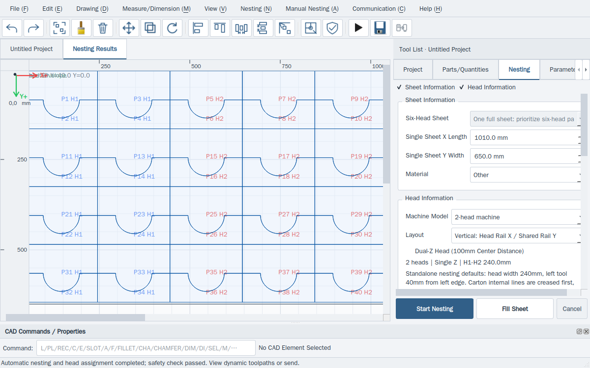
Nest actual contours and inspect the result · Actual software interface
Actual software interface · Nest actual contours and inspect the result
04

Turn a useful arrangement into reusable preparation

Compare actual nested counts, material utilization and retained groups. Reuse still undergoes current geometry, quantity, angle and machine-safety checks.

Test your own irregular parts

Get mCAD and compare individual, grouped and mixed layouts using real contours.

Get mCADDiscuss drawings and nesting ↗Help centre ↗
mCAD · Compare quantity, time and executable motion together

Test your actual parts before choosing a head count

Download mCAD and create separate projects with the real dimensions of your regular parts. Compare machine models and head counts with the same sheet, requested quantities, spacing and allowed angles.

  1. 01

    Import regular drawings or draw at actual millimetre dimensions; check closed outlines and internal holes or slots.

  2. 02

    Create a separate project for each machine configuration and set sheet size, physical head count, participating heads, margins and spacing.

  3. 03

    Nest the same parts by quantity or fill-sheet mode; record actual nested counts and inspect head assignments.

  4. 04

    Pass each project’s safety check and generate dynamic toolpaths; compare estimated time, parallel head use, waiting and rapid travel.

  5. 05

    Review shared-rail, physical head spacing and actual travel constraints, then compare additional heads with a lower head count.

Compare quantity, time and executable motion together

A denser layout or more heads alone cannot prove faster cutting. Compare successfully planned current results with confirmed material thickness, tools, speed mode, shared rail and travel limits.

Doubling the head count does not guarantee double productivity. If large regular parts cannot synchronize within shared-axis and safety-spacing constraints, fewer heads may suit them better. Standalone estimates support comparison; machine selection still requires actual parameters and test cuts.
Validate a configuration with your regular parts ↗