The densest layout is not always the fastest
Rapid travel, waiting, tool lift and lowering, curve speed and head coordination all affect cutting time. Material utilization alone misses batch counts and actual process conditions.
Cutting preparation turns a nested layout into routes the current machine can execute. mCAD validates the layout and generates toolpaths; the main program reviews planning and time estimates with job quantities, material and speed mode.
Rapid travel, waiting, tool lift and lowering, curve speed and head coordination all affect cutting time. Material utilization alone misses batch counts and actual process conditions.
Use validated processes for foam, sponge and other soft sheet stock cuttable with an oscillating knife. Sealing, insulation or honeycomb applications need blade, thickness and test-cut confirmation first.
Plan with the current heads, travel limits, shared rail, blades and individual Z work points. After saving or transfer, the target main program must still confirm parameters and on-site conditions.
Illustrative animation, not a live machine. Actual processing depends on software checks and site conditions.
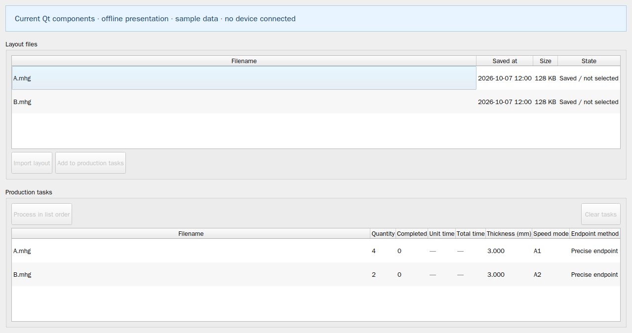
Review job quantities, completed progress, routes and planned time. Estimates come from successful current planning and support comparison and scheduling; actual cycle time requires production validation.
Start with one set of parts and compare quantities, routes and estimates under the current process.
Get mCADDiscuss jobs and processes ↗Help centre ↗Download mCAD and create separate projects with the real dimensions of your regular parts. Compare machine models and head counts with the same sheet, requested quantities, spacing and allowed angles.
Import regular drawings or draw at actual millimetre dimensions; check closed outlines and internal holes or slots.
Create a separate project for each machine configuration and set sheet size, physical head count, participating heads, margins and spacing.
Nest the same parts by quantity or fill-sheet mode; record actual nested counts and inspect head assignments.
Pass each project’s safety check and generate dynamic toolpaths; compare estimated time, parallel head use, waiting and rapid travel.
Review shared-rail, physical head spacing and actual travel constraints, then compare additional heads with a lower head count.
A denser layout or more heads alone cannot prove faster cutting. Compare successfully planned current results with confirmed material thickness, tools, speed mode, shared rail and travel limits.
Doubling the head count does not guarantee double productivity. If large regular parts cannot synchronize within shared-axis and safety-spacing constraints, fewer heads may suit them better. Standalone estimates support comparison; machine selection still requires actual parameters and test cuts.
Follow the drawing, nesting and job-planning workflows relevant to your parts and machines.
When drawings, quantities and machine settings are handled separately, a compact layout may still be impossible to cut. Shared rails, head travel, physical spacing and tool processes need to be checked together.
↗02Open outlines, incorrect dimensions or missing group members affect nesting. Repair the drawing, then recognize and save useful manually placed groups for later complete-group reuse and remaining single parts.
↗03Rapid travel, waiting, tool lift and lowering, curve speed and head coordination all affect cutting time. Material utilization alone misses batch counts and actual process conditions.
↗04Large regular parts, different contours or narrow gaps can restrict parallel work. Non-cutting heads remain physical objects and need reachable parking positions and avoidance checks.
↗05An import, a visible layout or a Send click does not by itself prove correct dimensions, valid routes or a saved host job. Review the current result and actual receipts at each step.
↗