FAQ and cutting-head accuracy checks
Check each head using the actual test-cut, automatic backlash measurement and W-zero calibration functions.
Carry out these steps in the installed production control software. This webpage gives instructions and cannot operate a machine. Figures show software templates or diagnostic schematics, not photographs of cut samples.
1. Run the actual test-cut function
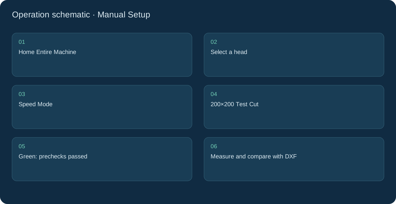
- Open “Manual Setup”, check that the controller is connected and ready, and complete “Home Entire Machine”. Fit the correct blade, secure the test material, and verify tool working points and actual material thickness.
- Click the head to check, such as H1 or H2, in the machine diagram. Select an enabled “Speed Mode” for the material and thickness, and check “Session Endpoints”. Keep material, blade and mode conditions consistent when comparing heads.
- Click “200×200 Test Cut” and move the pointer over the machine diagram to preview a 200×200 mm region. A frame turns green only after production prechecks pass. Click it, verify the head, thickness, speed and endpoint rules, then confirm the real cut.
- Wait for the cut to finish and all axes to stop. Internal shapes and the surrounding circle are cut first; the 200×200 mm frame is a separate final job. This test does not save speed-learning results.
- Before motion starts, the software saves a millimetre DXF from the same geometry used for the cut, under Documents/MultiHeadCutSuite/TrialCutDxf. Open it in mCAD to check drawing dimensions. A save failure prevents the cut from starting.
- Repeat for each head and record the head number, material, thickness, speed mode and measurements. Use “New Sheet” to clear occupied regions only after physically replacing the sheet.
2. Judge the cut samples
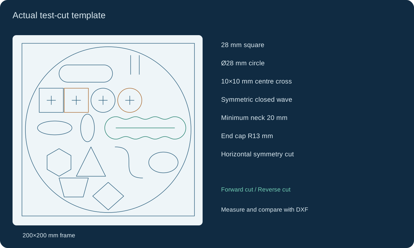
- Measure squares and circles cut in opposite directions. Both directions should produce matching dimensions consistent with the saved DXF. Template squares have 28 mm sides, circles are Ø28 mm, and the frame is 200×200 mm. Apply the tolerance agreed for the material and process.
- Inspect the central crosses inside the squares and circles. Opposite arms should meet continuously without lateral offset. Each template cross is 10×10 mm, made of four 5 mm strokes from the centre outward.
- Inspect the closed wave against its horizontal symmetry cut. Upper and lower contours should be mirror images and the opposite feed directions should agree. The template has a 20 mm minimum neck and R13 mm end caps. Pinching, steps or asymmetry require investigation.
- If dimensions, crosses or the wave disagree, check backlash first, then W zero and Z installation. Keep the sample with its DXF so you can repeat the test under the same conditions after corrections.
3. Confirm automatic backlash calibration first
- Check for valid automatic measurements of the common rail, head rail, Z and W axes relevant to the head, with compensation saved through the manufacturer’s commissioning procedure. Ask the manufacturer to recheck missing calibration or an adjusted transmission.
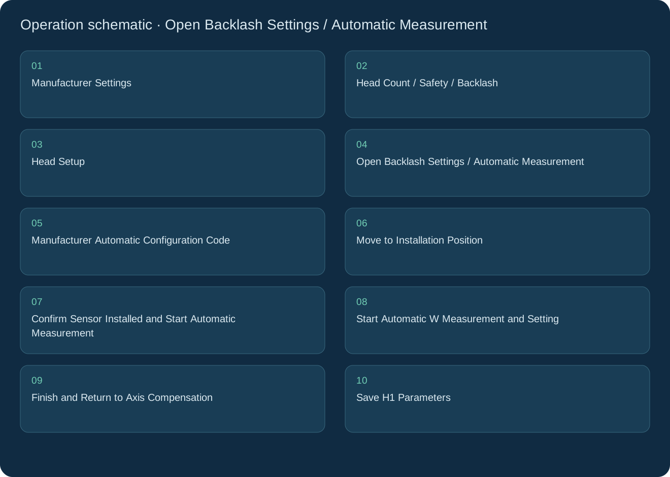
- With manufacturer access and the machine stationary, open “Manufacturer Settings” → “Head Count / Safety / Backlash”, select “Head Setup”, then click “Open Backlash Settings / Automatic Measurement”. Enter the valid code supplied by the manufacturer in “Manufacturer Automatic Configuration Code” to open the automatic axis-compensation dialog.
- For a linear axis, choose the installed sensor and COM port, then “Connect”. Select the axis and “Move to Installation Position”. After installing the sensor as specified, choose “Confirm Sensor Installed and Start Automatic Measurement” and wait for a valid result.
- For W, check that the axis is homed, its origin sensor is configured and all axes are stationary, then use “Start Automatic W Measurement and Setting”. This uses the W origin sensor; it does not need the linear-measurement SDL sensor or a COM port.
- When the required measurements pass, click “Finish and Return to Axis Compensation” to bring the results back. Check the values, then click the head’s save button at the bottom, for example “Save H1 Parameters” for H1, to write the configuration. The H number identifies the selected head; measurement without saving is not complete.
- A failed measurement, inadequate repeatability or unsaved compensation is not a completed calibration. Resolve the displayed fault and mechanical cause first. Repeat the test cut after calibration; if errors remain, check W0 and Z perpendicularity.
4. Find the best aligned line using W0 calibration
- Return to “Manual Setup”, select the head and an appropriate “Speed Mode”. Finish or “Cancel This Learning/Trial Cut/Calibration” any existing session and complete machine homing.
- Enter a positive sweep angle and “Angular Step” in “W-Axis Zero Calibration”. The positive angle must be greater than 0 and no more than 15°; the step must be positive and no larger than the full positive-to-negative span. Example: 5° with 0.5° steps gives 20 numbered conditions from +4.5° to −5°.
- Click “Select W0 Calibration Region”, preview a 200×200 mm region, and click a green frame that passes prechecks. Verify the confirmation details before executing the real calibration cuts.
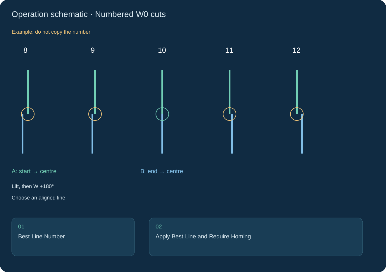
- Each number has two inward cuts: A runs from one end to the centre; the blade lifts and physically turns 180°, then B runs from the opposite end to the same centre. Wait for all numbered conditions to finish and the controller to stop.
- Inspect the central joins and choose the most continuous line with no lateral offset between opposite cuts. Enter its number in “Best Line Number”. If none qualifies, check Z perpendicularity, the blade and backlash; do not pick an arbitrary line to conceal a mechanical problem.
- Click “Apply Best Line and Require Homing” and confirm the head, line number and signed correction. The software saves the new W-zero offset and immediately invalidates the previous homed state. Complete “Home Entire Machine” again before running another 200×200 test cut.
5. Check Z perpendicularity and repeat the test
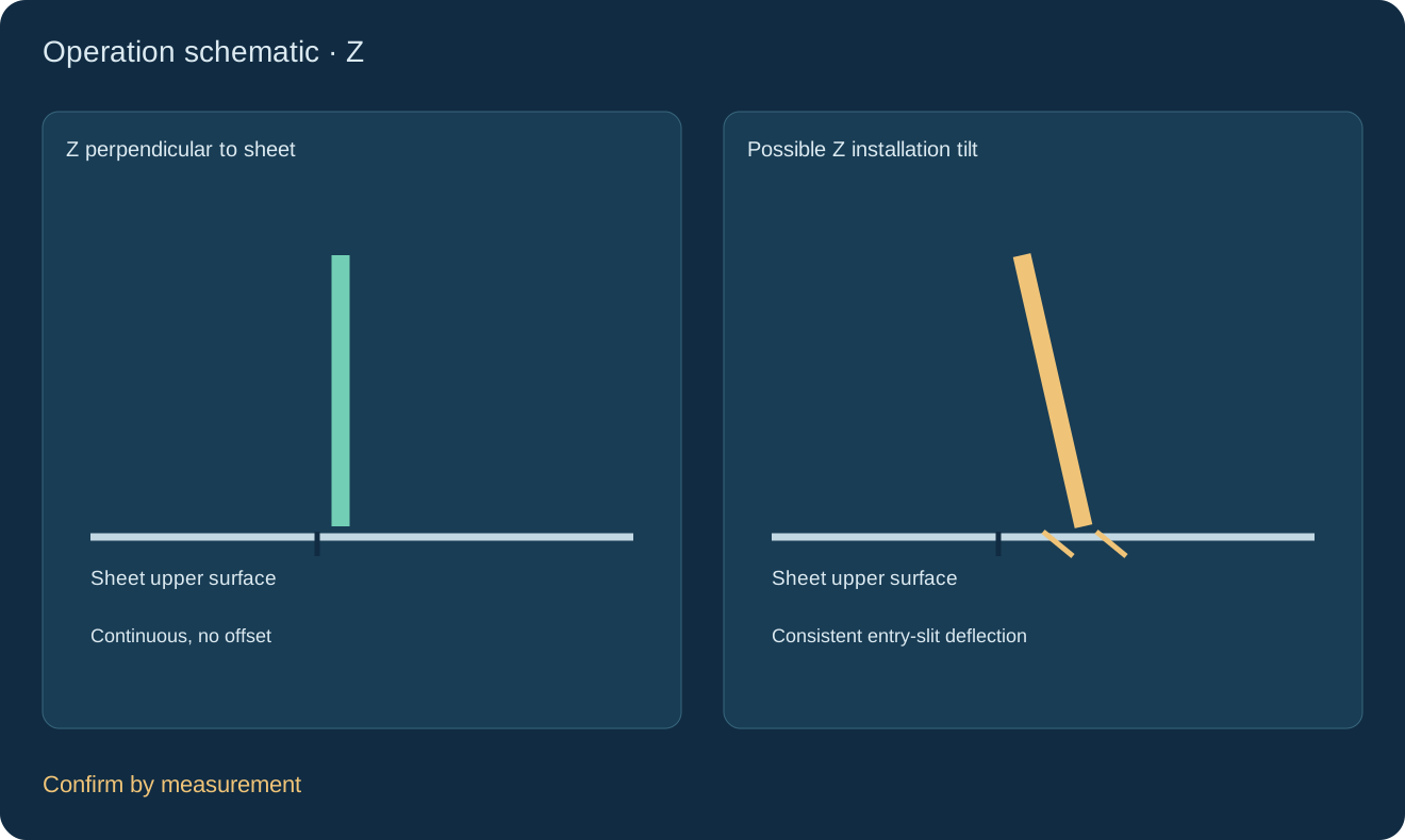
- Inspect both the entry slits and central joins on the W0 numbered sample. If entry slits keep leaning toward the same direction on the material across different numbers or opposite blade orientations, record it as a clue to Z or head installation tilt.
- Have the manufacturer measure the perpendicularity of Z travel to the sheet’s upper surface using a square, indicator or suitable method. Also check blade clamping, tool geometry and material holding. A cut slit alone cannot uniquely diagnose Z tilt.
- Correct installation errors following the manufacturer’s procedure. A W-zero change cannot repair a non-perpendicular Z installation. Then repeat W0 calibration, choose a truly aligned opposite-cut line, apply it and home the entire machine again.
- Repeat the trial with the same material, thickness, blade and speed mode. Record a pass only when opposite-direction dimensions match the DXF, crosses are continuous, the wave is symmetric and the agreed tolerances are met. Send remaining errors, samples, DXF and head records to the manufacturer for analysis.
FAQ
Can mCAD run on its own?
Yes, for drawing, nesting and dynamic path demonstrations. Production connections still require actual machine parameters, head configuration and software authorization.
Does downloading enable machine control?
No license or machine authorization is granted by a download. Use a manufacturer-approved release and configuration, then complete connection, homing, planning and on-site confirmation.
Why learn multi-part combinations?
Save an arrangement chosen by an operator. When part features, sheet, quantity and machine conditions match, reuse it first and then fill the remaining space.
Can I prepare work for multiple machines?
Use independent projects to prepare nesting and tasks for different machines. Check the target machine and actual parameters when sending.
How are two sheets handled?
Equal-size sheets can reuse sheet 1 geometry, with fresh allocation and checks for sheet 2’s heads. Other conditions are handled for the corresponding sheet.
When can I download an installer?
Once the administrator publishes a formal mCAD installer, register your company and email to obtain a download link. Registrations are saved even before release.